Fridge Flight Tracker
I really had to know what planes were flying over my house
Date:
[]
Views: [37872]
Categories:
[projects]
Tags:
[python],
[flight-tracking],
[raspberrypi]
I'm currently quite annoyed as there's a company sprung up selling clones of these with no credit and passing them off as their own design. I've written up about their shenanigans over here: Flight Radar LED Ripoff
tl;dr
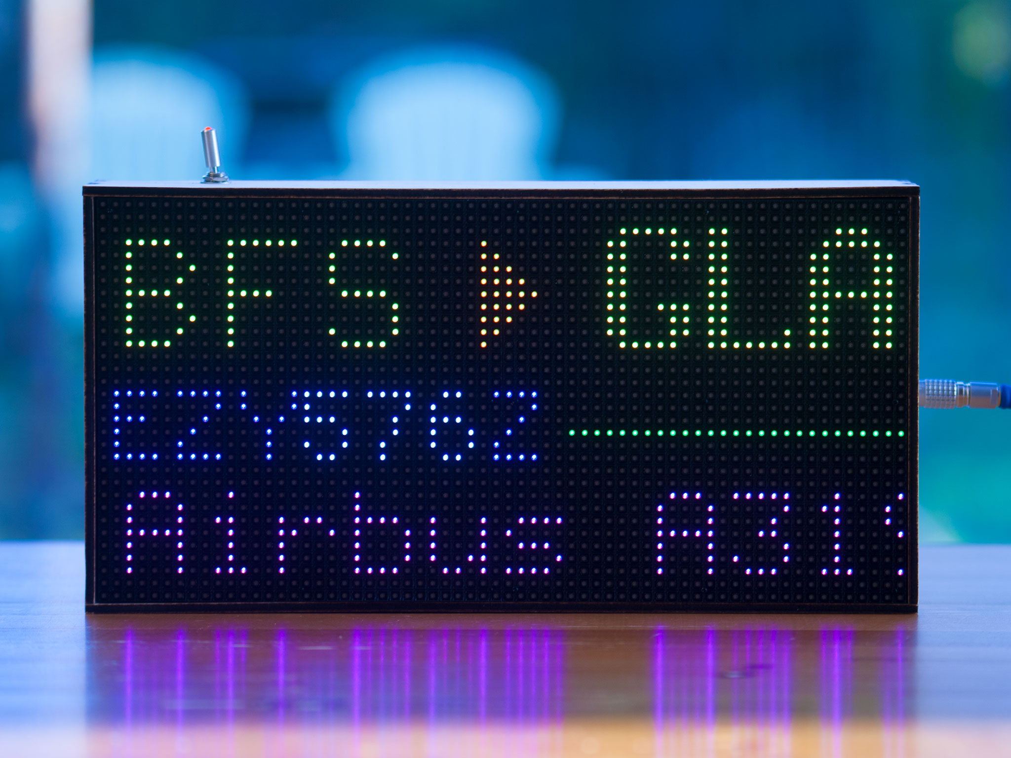
I've put together a wooden box with a dot matrix screen which uses a Raspberry Pi and FlightRadar24 to let me know what aircraft are over my house. It has some big magnets on the back which let me mount it to my fridge. When there's nothing overhead it shows the date, time and the temperature outside. It's also quite pretty.
What, why?
Once the lockdown restrictions started to ease off my wife and I quickly realise the serene neighborhood we'd moved into was directly on the flight path for Glasgow airport. We're far enough away that the windows don't always shake but close enough to start noticing the difference in how each plane sounds. How cool would it be to say, "that sounds like a Engine Alliance GP7000, must be an Airbus A380"? Not very, but that didn't put me off building something to tell me what aircraft are nearby.
Plan A was a split-flap display like at the airport, but that was either going to be more effort or more money that I was willing to put in. Instead I've pieced together something far sleeker.
The build
Custom box
As soon as I seen the 32x64 Adafruit LED RBG Panels on Pimoroni I knew exactly what I wanted the final product to look like. As close to a featureless box made from a light wood with the matrix display flush with the front, just deep enough to fit the electronics. I wanted it to float weightlessly on my fridge with a single slightly fancy looking cable running into it. I took to illustrator, made up a plan and went searching for a local carpenter to help me build what was in my head. Thanks to LinkedIn I found Lee Turnbull who is an engineer and a fantastic joiner.
![]()
![]()
![]()
After sending him my plan he put together a design and with a little refinement Lee suggested going for interlocking laser cut birch. Inside the box there's some big screws driven into the standoffs to give the screen's magnets something to attach to. On the back of the box there are some screws with neodymium magnets built in which allow the screen to be mounted to my fridge. There's then a bit of neoprene attached to the back of the box to prevent it from slipping once up on the fridge.
Once he was done the only thing standing between me and the box was the Hermes courier. After a week of lost-parcel-terror the finished product was delivered to much rejoicing and swearing about how crap Hermes are.
(Pro tip: if you're too Scottish sounds for a poorly implemented voice-recognition system to direct you to a human, I recommend using the text-to-speech feature on your computer)
Electronics
Thankfully the tricky electronics required to run the screen are taken care of by another great product on Pimoroni, the Adafruit RGB Matrix Bonnet for the Raspberry Pi. This also cemented the decision that this project was going to be built around a Raspberry Pi. I went with a Pi Zero W to minimise how much space would be needed inside the box.
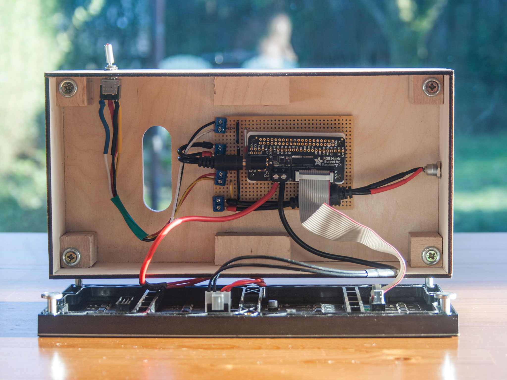
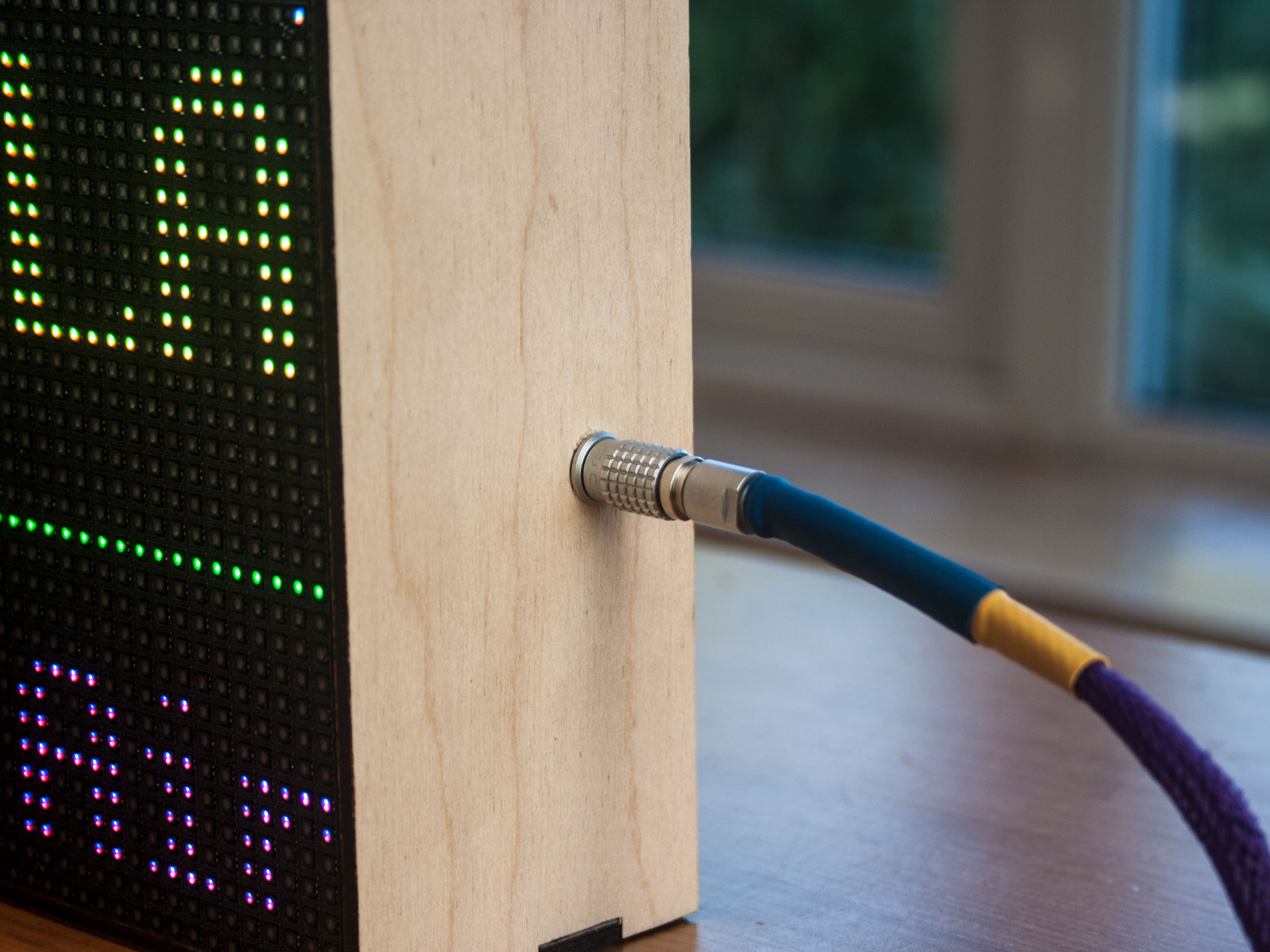
Power comes from a 5v supply brick normally used for powering LED light strips. That cable is nowhere near tasty enough for the project so the plug was been swapped out for a Lemo 0B push-pull connector and paired with it's panel-mount partner. Any excuse I'll use these, they are gorgeous - totally the wrong kind of connector for the job, but gorgeous.
I've added a little extra pizzazz to the cable by jacketing it with some purple braiding and a little heat-shrink for strain relief.
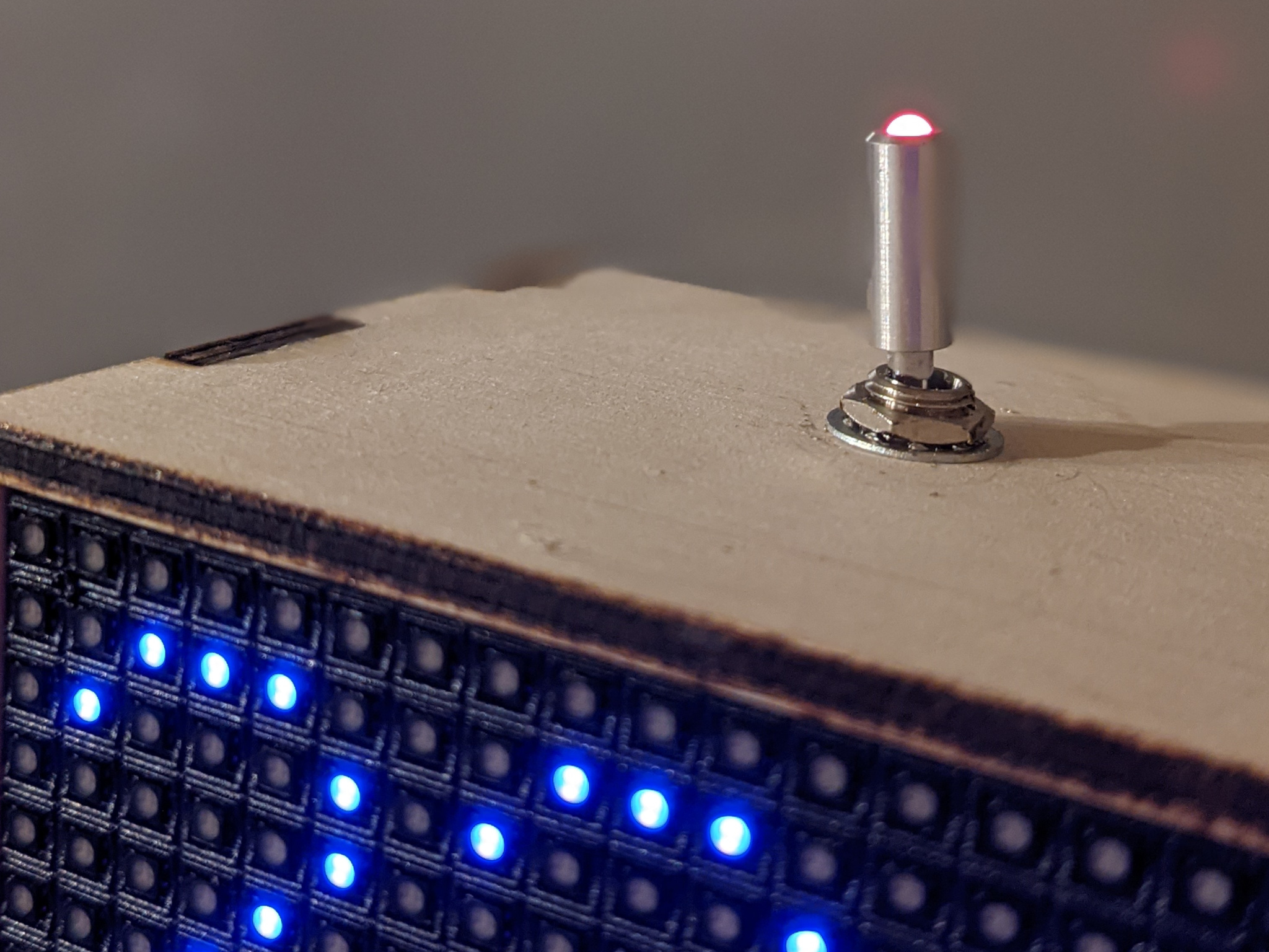
A power toggle wasn't in the original plan but I figured an extra LED and a switch that looks like a tiny antenna wasn't to be passed up. The switch is a NKK SPDT with a little red LED at the end of it.
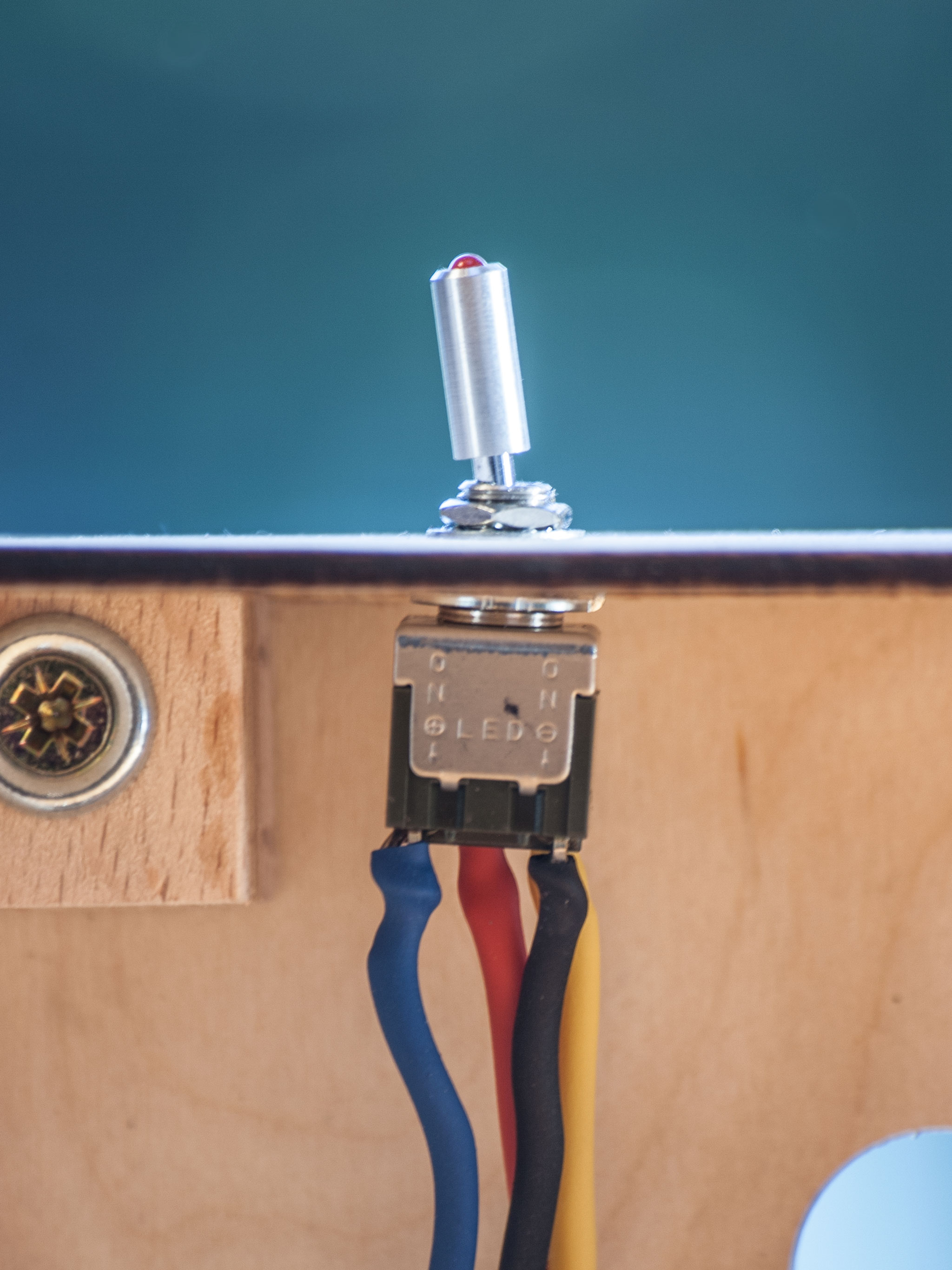
To keep everything tidy inside the box I used a small strip of Veroboard to pull together:
- Incoming power
- On/Off switch
- Raspberry Pi power input
- LED and current limiting resistor
To bring power from the panel connector to the Veroboard I used the left over length of cable from the power supply with the ferrite choke. Leaving the choke on helps to clean up the supply voltage. The remaining part of the cable with the barrel jack on it is used to hook up the Raspberry Pi to the Veroboard. So it doesn't get fried the LED needs a little inline resistor to limit current, a back-of-an-envelop calculation and a rummage through my toolkit revealed a 330R would do the job.
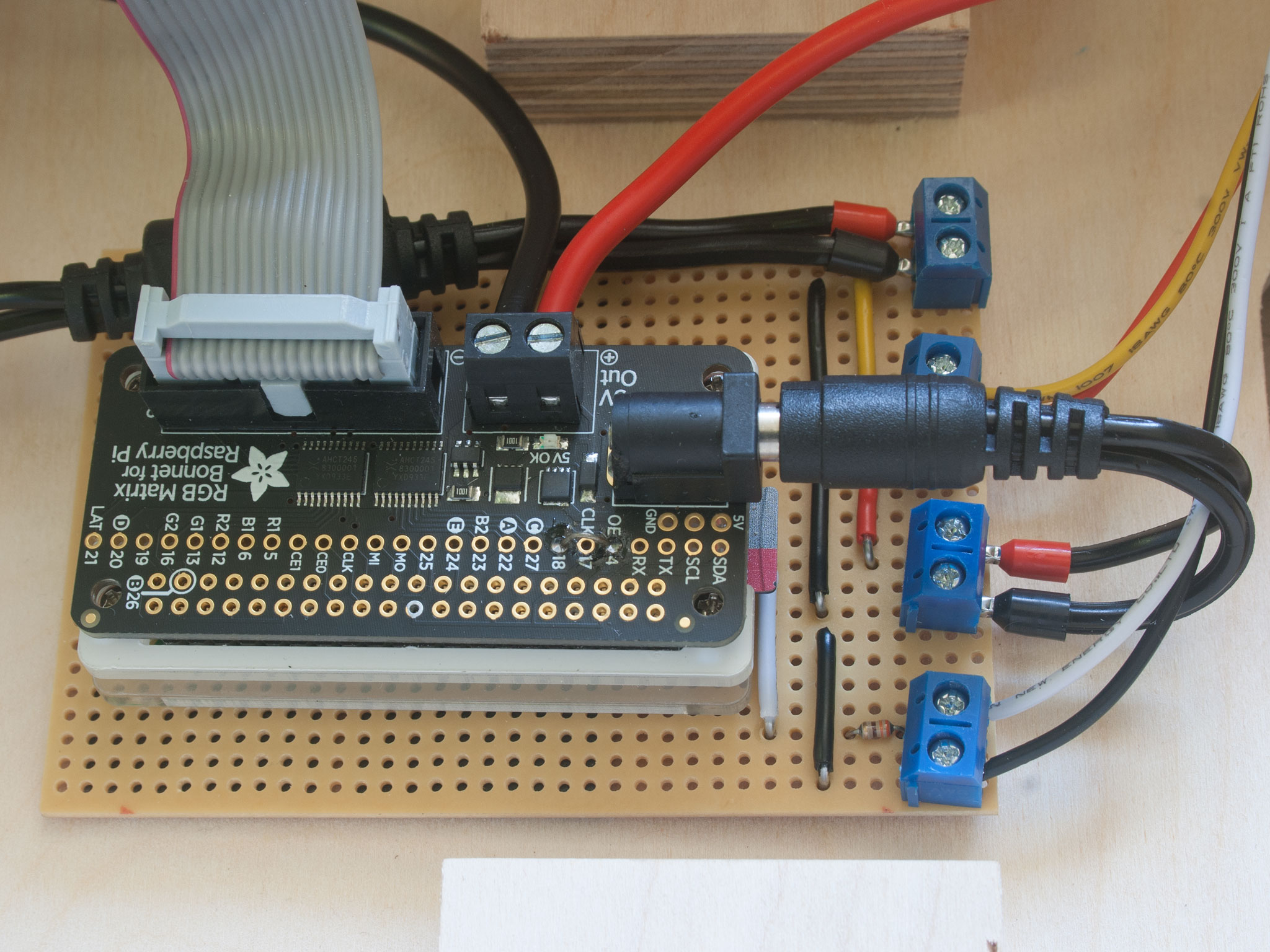
Everything is assembled using 18AWG single core prototyping wire and some terminal screw blocks. All the unused Veroboard has been isolated so that I can safely use a few layers of double-sided padded tape to mount the electronics to the back of the box. I used more of the same tape to fix the Raspberry Pi to the Veroboard.
Software
At first I was going to use the C++ bindings that are available on Github for the display as an excuse to brush up on my C++, but then CMake quickly dissuaded me of such a silly notion. God I hate a CMakeLists.txt file.
Thankfully the fantastic people providing these drivers have also made a Python version available. I also followed their instructions to up the quality of the display by soldering a little bridge between two pins on their bonnet so the Raspberry Pi's sound adaptor can be used to regulate the PWM of the display circuitry.
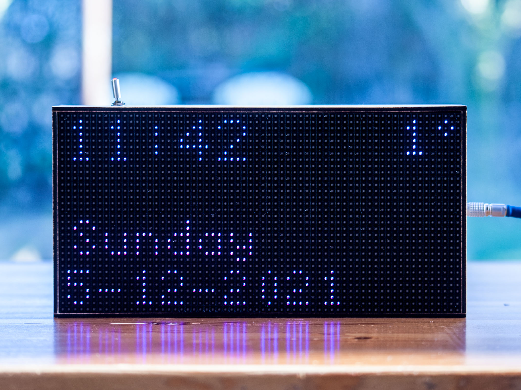
With the electronics hooked up I designed a simple animation engine for this matrix display. I'm really happy with how this code came together - each element of the screen is handled by a different method in my application, these include:
- A flight's source and destination
- The flight number
- A scroller featuring the make and model of the plan
- Shapes and lines to help divvy-up the information
- A flashing pixel to show when data is being requested
![]()
Frame-by-frame, as the engine spins it's told how often to each run method: some run every single frame (the scrolling text), some every second frame (pulsing loading light), sometimes only once every second (the temperatures data).
This is what's going on in module display (link to source)
As an example, this is what it looks like increasing and decreasing the brightness of the pixel used to indicate data is being loaded. This code is triggered on every 2nd frame (@Animator.KeyFrame.add(2)). The number of times this function has been called is passed in as variable count and if we return True this counter is reset. This functionality is used throughout the application to control animations.
@Animator.KeyFrame.add(2)
def loading_pulse(self, count):
    reset_count = True

    if self.overhead.processing:
        # Calculate the brightness scaler and
        # ensure it's within a sensible range
        brightness = (1 - (count / BLINKER_STEPS)) / 2
        brightness = 0 if (brightness < 0 or brightness > 1) else brightness

        self.canvas.SetPixel(
            BLINKER_POSITION[0],
            BLINKER_POSITION[1],
            brightness * BLINKER_COLOUR.red,
            brightness * BLINKER_COLOUR.green,
            brightness * BLINKER_COLOUR.blue,
        )

        # Only count 0 -> (BLINKER_STEPS - 1)
        reset_count = (count == (BLINKER_STEPS - 1))

    else:
        # Not processing, blank the square
        self.canvas.SetPixel(BLINKER_POSITION[0], BLINKER_POSITION[1], 0, 0, 0)

    return reset_count
Flight information is being polled using the official FlightRadar24 python module. I've wrapped this up in some of my own code, overhead.py (link to source) to help format the data and perform some rate limiting on how many requests I'm making to FlightRadar24.
When there's no flight overhead the screen displays the current date, time and the temperature outside. The temperature information comes from another of my websites, taps-aff.co.uk. The code for pulling this data is in temperature.py (link to source)
Finished Product
I couldn't be happier with the finished unit. Lee done an amazing job with the case and it sits happily up on the fridge without slipping.
![]()
It took a while for everything to come together but making this exactly as I wanted, down to the colour of the internal wiring, was 100% percent worth the effort. I'm really happy to have seen this finished exactly like the daft idea which had initially popped into my head.
Most importantly I can now hear the difference between a Boeing and an Airbus.
Future improvements
Software is never finished, only abandoned. With that in mind, I'm probably going to be tweaking the animation for some time. Colours, speeds, everything is fair game.
For the electronics, first thing I want to do is make the LED in the switch flash. This would look much cooler than the pulsing loading pixel. To do this I'm going to need to add another resistor and a transistor to the Veroboard - that'll need need hooked up to one of the GPIOs on the Raspberry Pi. I don't expect to get round to this any time soon!
License Update (April 2025):
Fridge Flight Tracker is now released under GNU GPL v3.0. Unfortunately, I’ve had to add this license because some people have been selling these as their own with zero attribution. You’re still welcome to use, modify, and share the code just keep it under the same license and retain my copyright and license notice. After all, open-source projects like this are our CVs: passing off someone else’s work as your own robs us of the chance to showcase what we can do.